

The last step is to make the cam. This lesson exports it in the formats a printer and a CAD program take.
Open CamLab, click New and switch to Advanced.
1. The part
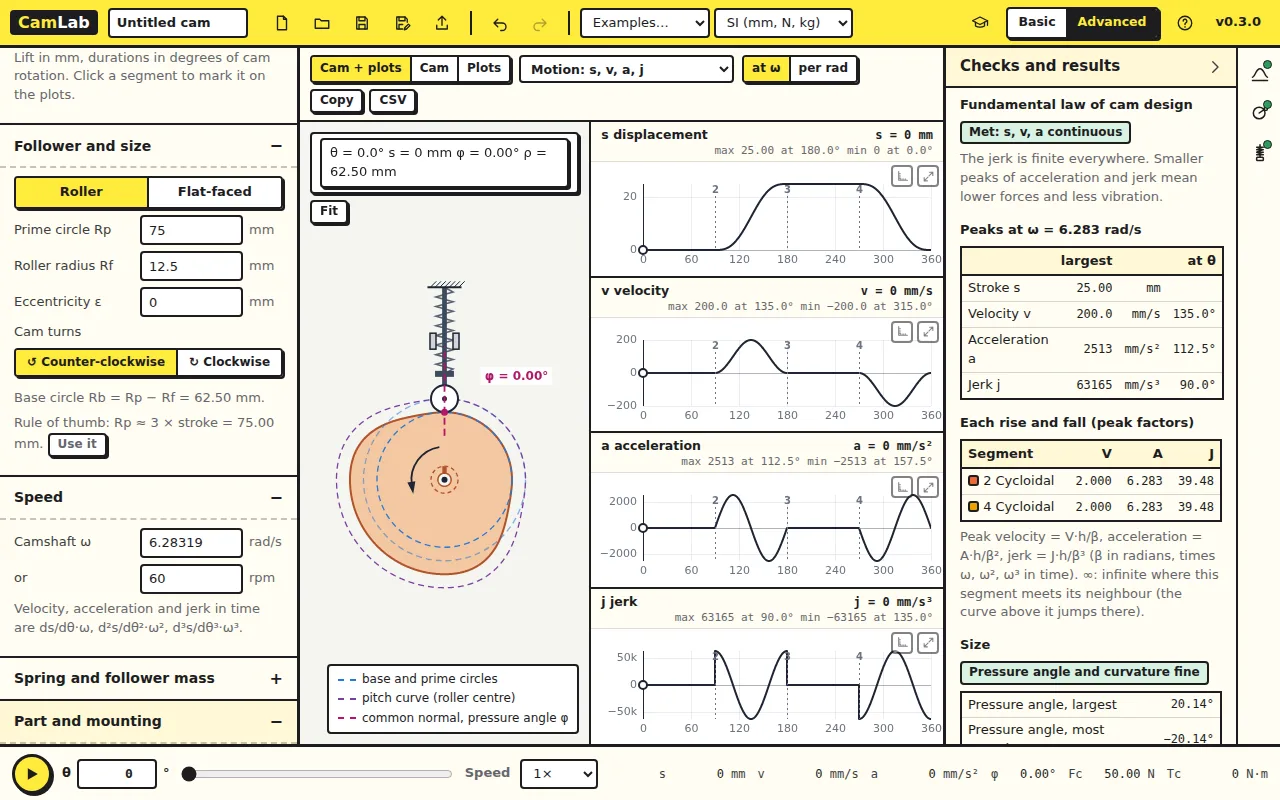
Open Part and mounting on the left. Thickness and Shaft Ø set the part; Mounting chooses how the cam fixes to its shaft: a plain bore, a keyway, a D-flat, a hub with a set screw or a bolt flange. Choose Hub with set screw. The cam view shows the hub.
2. Export
Click Export in the top bar.
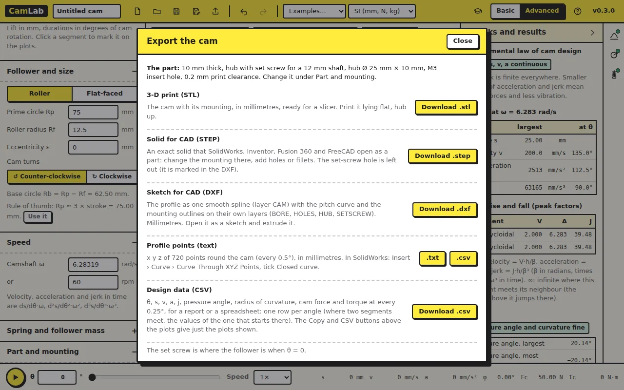
- 3-D print (STL): the cam with its mounting, in millimetres, for a slicer. Print it lying flat. The default Print clearance of 0.2 mm makes the bore a little larger than the shaft, as FDM printing needs.
- Solid for CAD (STEP): an exact solid that SolidWorks, Inventor or Fusion 360 open as a part.
- Sketch for CAD (DXF): the profile as one smooth spline on layer CAM, with the pitch curve and the mounting on their own layers. Open it as a sketch and extrude.
- Profile points (text): x y z of 720 points round the cam, every 0.5°. In SolidWorks: Insert › Curve › Curve Through XYZ Points, ticking Closed curve.
- Design data (CSV): θ, s, v, a, j, pressure angle, radius of curvature, cam force and torque every 0.25°, for a report.
Check your numbers
In the profile points file, the first point is (0, 62.5, 0): the base circle radius Rb = Rp − Rf = 75 − 12.5 = 62.5 mm, at the top of the drawing. The furthest point is at 87.5 mm, Rb plus the 25 mm lift. The mounting feature (here the set screw) marks where θ = 0 is on the printed part.
Try this
Export the STL and open it in your slicer. How long does the cam take to print, and would a bolt flange change that?
Answer
It depends on your printer; a 10 mm thick cam of this size takes an hour or two. A flange adds a thin disc and four holes, so little time. What matters more for a working cam is the orientation (flat, so the profile is drawn by the nozzle's path and not by layer steps) and the clearance of the bore.