

When the design is right, take it out of LinkLab: the links as CAD sketches to extrude and print, and the numbers for a report.
Start from fourbar.linklab.json. Set θ₂ to 60 and click Export in the top bar.
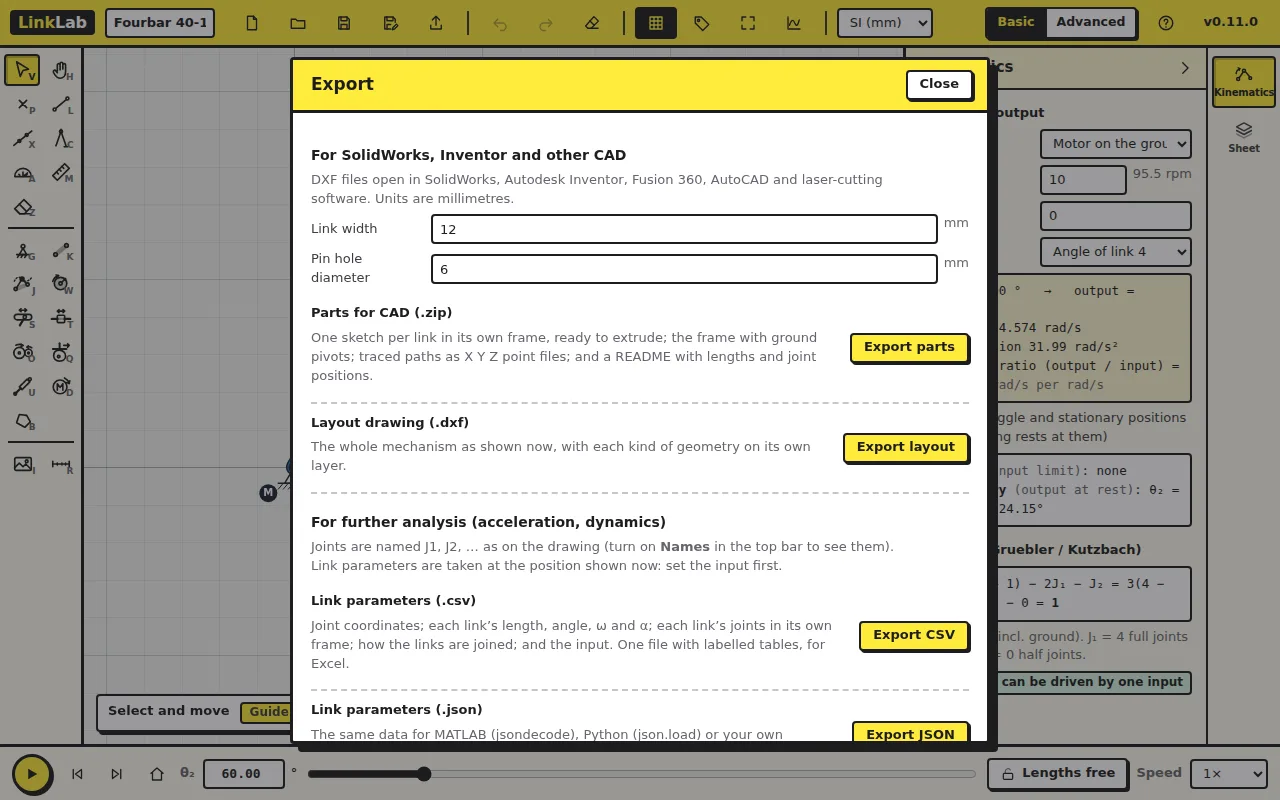
1. Parts for CAD
Link width and Pin hole diameter set the shape of every link.
Export parts writes a zip with one DXF per link, drawn in the link's
own frame and ready to extrude: Link2.dxf, Link3.dxf, Link4.dxf, a
Frame.dxf with the ground pivots, a Layout.dxf of the whole mechanism,
the traced path as Path_P1.txt (X Y Z points, for a curve in CAD), and a
README.txt with the lengths and joint positions.
In SolidWorks or Inventor: new part, new sketch, insert the DXF, extrude. Everything is in millimetres.
2. The layout drawing
Export layout writes one DXF of the mechanism as drawn, with each kind of geometry on its own layer: LINKS, PIN_HOLES, CENTRE_LINES, GROUND, PATHS and NOTES. Use it for a drawing sheet, or to lay the parts out for laser cutting.
3. The numbers
Export CSV writes the link parameters at the position shown, with labelled tables for a spreadsheet: joint positions, velocities and accelerations; each link's length, angle, ω and α; masses; and how the links are joined. Joints are named J1, J2, … as on the drawing (turn on Names in the top bar to see them).
| In the CSV at θ₂ = 60° | |
|---|---|
| Link 2 length | 40 mm |
| Link 4 length | 80 mm |
| J3 (point A) | 20, 34.641 mm |
The coupler is a plate with three joints, so its row has no single length; its joint-to-joint distances are in the LINK GEOMETRY table.
Export JSON gives the same data for MATLAB or Python. Export data, in the plots, gives every plotted quantity over the whole cycle.
Try this
Open Link3.dxf in your CAD program and check the distances between its
three holes: the two pins and the traced coupler point (a hole for a pen,
or for a link added later).
Answer
120 mm between the two pins (the coupler length). The coupler point's hole is midway between them, 60 mm from each.