

Real pins are smaller than their holes. This lesson shows what that does to the rocker's angle, and which pin matters most.
The Tolerance tab is in beta: its numbers are estimates, good for comparing designs and finding the pin to improve.
Start from fourbar.linklab.json. Switch to Advanced, open the Tolerance tab and set θ₂ to 60.
1. The play
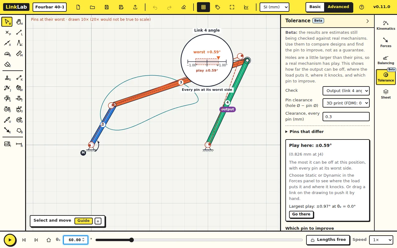
Under Pin clearance, choose 3D print (FDM): 0.300 mm: each hole is 0.3 mm larger than its pin, so a pin can sit up to 0.15 mm off centre in any direction. With Check on the output (link 4's angle), the panel reads:
| Pin clearance 0.3 mm at all four pins | LinkLab |
|---|---|
| Play at θ₂ = 60° | ±0.59° |
| Largest play over the cycle | ±0.97° at θ₂ = 0° |
The play is largest at θ₂ = 0°, where the transmission angle is smallest (lesson 2): the same geometry that passes force badly also passes error well. The magnifier on the drawing shows the play here, ±0.59°, shaded on a scale from −1° to +1°, and the dashed links show the mechanism with every pin at its worst side, drawn larger.
Check your numbers
Move each pin to the edge of its hole in turn, in every direction, solve the fourbar with the shifted pins, and take the largest change in θ₄. Sampling each pin at 24 directions (24⁴ cases) gives 0.592° at 60° and 0.969° at 0°.
2. Push it by hand
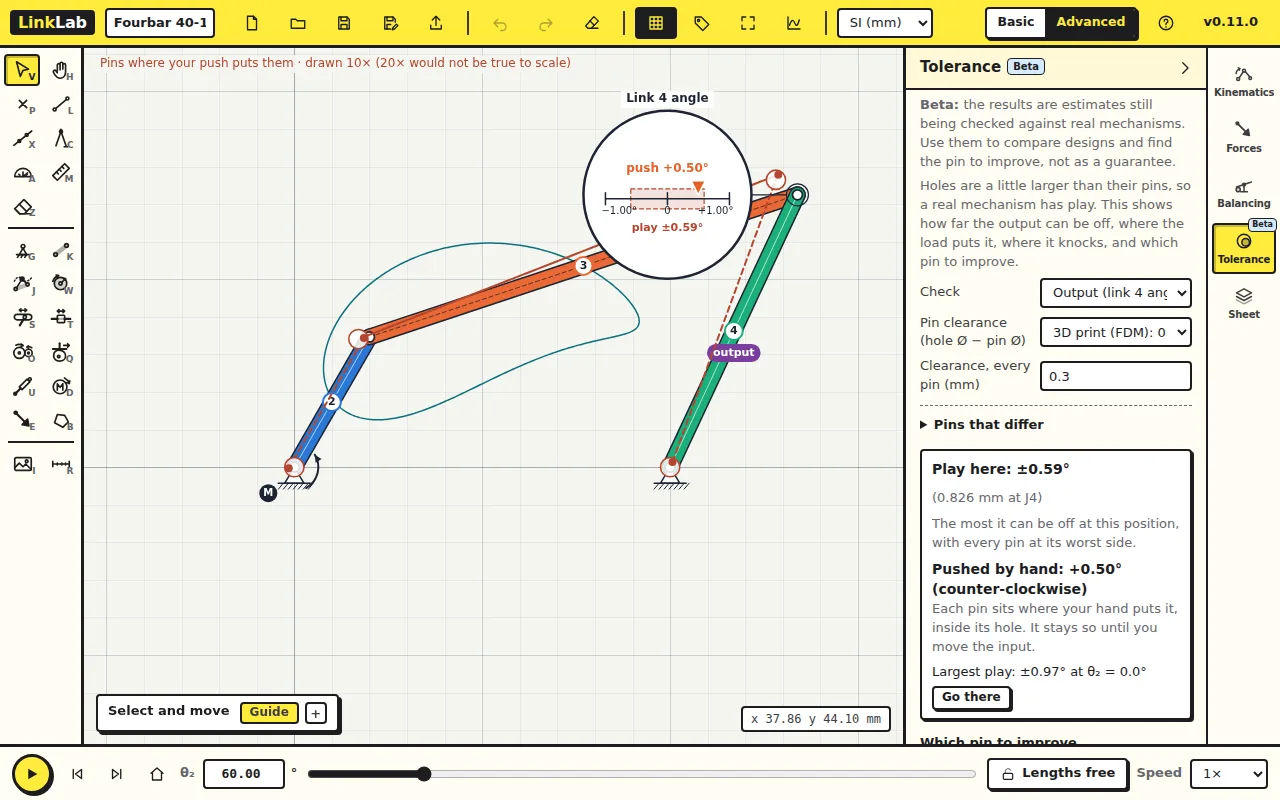
Drag the coupler on the drawing. The motor holds the crank, so the links can only move within their play; the dashed drawing follows your hand, and the panel reads Pushed by hand with the rocker's angle error. Push the other way and the pins cross to the other side of their holes. This is the backlash you would feel in the real mechanism.
3. Under the load
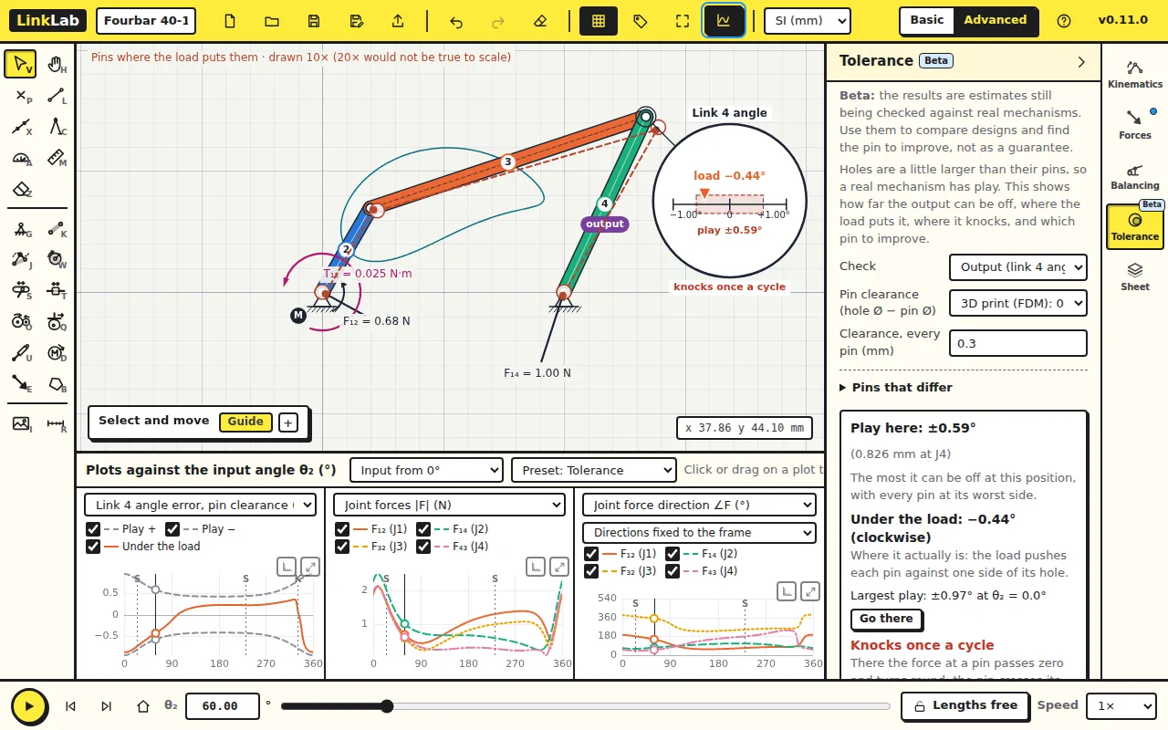
A running mechanism does not sit at random in its play: each pin is pushed to one side of its hole by the force at that pin. In the Forces tab choose Dynamic, then come back to Tolerance. Under the load gives the actual error at this position, −0.44°, and the panel reports Knocks once a cycle: at that position the force at a pin passes zero and turns round, the pin crosses its hole, and the rocker jumps.
The preset Tolerance in the plots marks the knock with a K on the error curve, next to the point where a joint force drops to almost zero.
4. Which pin to improve
Which pin to improve shows how much each pin contributes. Here all four count the same. Open Pins that differ and give J1 a ball bearing: 0.01 mm. The play drops from ±0.59° to ±0.45°.
Try this
Which single pin, given a bearing, reduces the play most? Try each.
Answer
For this fourbar all four pins contribute equally at 60°, because they form one loop with the same clearance, so each bearing takes off the same amount. In other mechanisms, and at other positions, the shares differ: the panel's bars show where a better pin pays.